Click the diagram to enlarge.
|
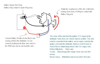
How about testing the distributor in the shop where it is not connected to any vehicle. This can be done by following the diagram here which will give an idea as to whether the distributor is good or bad by merely looking for sparks when the distributor is turned by hand (wear gloves ) as illustrated here.

A typical distributor test involves a couple of jumper wires, connectors and plug cable and a spark plug (and a pair of gloves to prevent shocks - notice the black item on the top right). The HT cable connection on the left uses one of the four nodes of the distributor cap which is connected to a spark plug and its body grounded at the negative pole seen here.
On turning the coupling key of the distributor driveshaft at the bottom, there will be sparks across the spark plug if the distributor is in working condition.
This test do not require removal of the distributor cap and utilizes one of the cap nodes. One of the concerns when testing on one of the nodes (at a time) is that while turning the distributor shaft, the HT voltage will spark and ground through the battery negative terminal but the remaining 3 nodes at the distributor end do not have a path to ground as it is not connected. This results in the HT voltage generated for the remaining 3 nodes sparking inside the distributor. This back surge of voltage within is detrimental if the tester continue to test in this manner over a long period of time. Normally there is no issue if the test is performed on just one turn of the distributor to check for arcing on one spark and stop after that.
 Another alternative is to remove the distributor cap and insert a spark cable directly into the only high tension node (see photo on left ) and connect the other end to a spark plug as prescribed above. This HT node is equivalent to the center node of most distributor cap where it distributes the HT voltage through the rotor arm and arc across the four nodes of the distributor. In this manner, when you turn the distributor shaft, the HT voltage will be channelled to the test spark plug above for all four segments when the distributor rotates.

A typical distributor test involves a couple of jumper wires, connectors and plug cable and a spark plug (and a pair of gloves to prevent shocks - notice the black item on the top right). The HT cable connection on the left uses one of the four nodes of the distributor cap which is connected to a spark plug and its body grounded at the negative pole seen here.
On turning the coupling key of the distributor driveshaft at the bottom, there will be sparks across the spark plug if the distributor is in working condition.
This test do not require removal of the distributor cap and utilizes one of the cap nodes. One of the concerns when testing on one of the nodes (at a time) is that while turning the distributor shaft, the HT voltage will spark and ground through the battery negative terminal but the remaining 3 nodes at the distributor end do not have a path to ground as it is not connected. This results in the HT voltage generated for the remaining 3 nodes sparking inside the distributor. This back surge of voltage within is detrimental if the tester continue to test in this manner over a long period of time. Normally there is no issue if the test is performed on just one turn of the distributor to check for arcing on one spark and stop after that.
 Another alternative is to remove the distributor cap and insert a spark cable directly into the only high tension node (see photo on left ) and connect the other end to a spark plug as prescribed above. This HT node is equivalent to the center node of most distributor cap where it distributes the HT voltage through the rotor arm and arc across the four nodes of the distributor. In this manner, when you turn the distributor shaft, the HT voltage will be channelled to the test spark plug above for all four segments when the distributor rotates.
No comments:
Post a Comment